Explore our production-grade cages built to comply with strict MSA, IEEE, and EMI requirements.
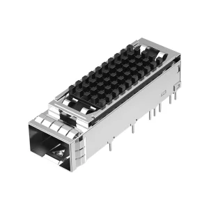
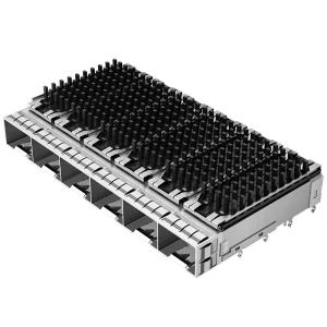
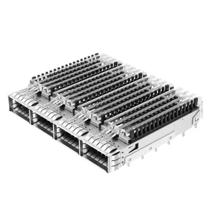
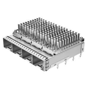
Ganged ports are optimized to handle critical signal paths from SFP, SFP+, and SFP28 transceivers, accommodating line rates from 1Gbps up to 28Gbps per channel. Designers favor the ganged arrangement for several reasons. Firstly, it offers a direct, low-latency thermal dissipation path. Heat generated by the optical modules is directed upwards through dedicated heat sink assemblies rather than being trapped in the lower layer of a stacked configuration. Secondly, the planar design simplifies trace routing on the underlying Printed Circuit Board (PCB), reducing the need for costly micro-vias and complex multilayer PCB stacks.
From an electrical perspective, maintaining Signal Integrity (SI) at speeds exceeding 10Gbps is highly sensitive to port geometry. A ganged SFP cage acts as an electromagnetic shield enclosing the sensitive electrical contact interfaces. The outer shell, typically manufactured from premium copper alloys (such as C7025) or stainless steel, features custom-designed EMI spring fingers and gasket configurations. These features ground the assembly to the bezel front panel and PCB, preventing radiated emissions from compromising adjacent signals.
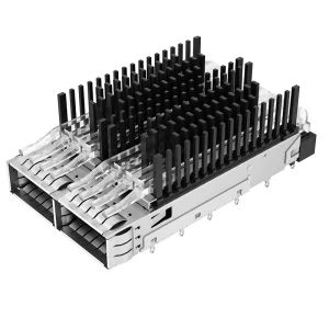
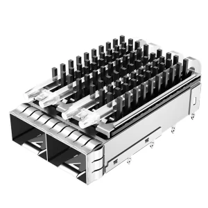
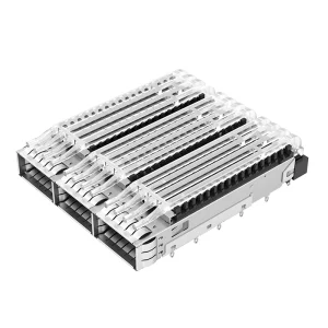
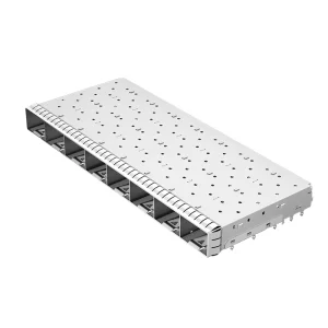
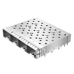
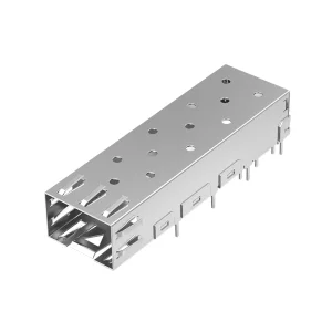
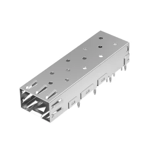
When integrating ganged SFP cages, hardware engineers must evaluate mechanical mounting styles, EMI containment levels, and thermal options. Ganged cages are available in configurations ranging from 1x2, 1x3, 1x4, to 1x6 and 1x8 ports. The table below details key parameters governing our standard and customized product lines:
| Parameter Type | Standard Specifications | High-Performance Capabilities |
|---|---|---|
| Housing Material | Copper Alloy / Stainless Steel (SUS 304) | Nickel-plated Copper Alloy (C7025) with selective gold plating |
| Mounting Style | Press-Fit (Elastic compliant pin / Eye-of-the-needle) | Through-Hole Technology (THT) Soldering |
| EMI Shielding Options | Standard spring fingers / Elastomer gaskets | Advanced dual-layer EMI spring finger contact array |
| Thermal Options | No heatsink / Simple clip-on pin fin heatsink | Custom heights (4.2mm to 13.5mm) with cylindrical & square fins |
| Data Rate Compatibility | SFP (1 Gbps) / SFP+ (10 Gbps) | SFP28 (25 Gbps) / SFP56 (56 Gbps PAM4) |
| Operating Temperature | -40°C to +85°C (Industrial Grade) | -40°C to +105°C (Extended Range / Automotive) |
Press-fit (compliant pin) terminal designs are preferred in modern telecom applications as they allow solderless board assembly. This method reduces thermal stress on neighboring PCB components and simplifies rework procedures. THT solder variants remain a reliable option for extreme shock and vibration environments, providing robust mechanical anchor points to the board substrate.
The deployment of 1xN ganged SFP cages is expanding globally, driven by infrastructure upgrades in enterprise networks, 5G base stations, and edge computing nodes. The market transition towards higher bandwidths—such as 25G SFP28 and 56G/112G interfaces—demands improved mechanical and electrical performance from the surrounding shielding cages.
In North America and Europe, hyperscale data center operators are driving the adoption of high-density ganged configurations with integrated heatsinks. These configurations are designed to manage the high thermal output of industrial optical transceivers operating under continuous loads. Concurrently, in Southeast Asia and the Middle East, the rapid roll-out of 5G cellular networks has created demand for ruggedized, EMI-shielded 1x2 and 1x4 ganged cages. These cages are deployed in remote radio heads (RRH) and baseband units (BBU) where they must withstand outdoor environmental conditions.
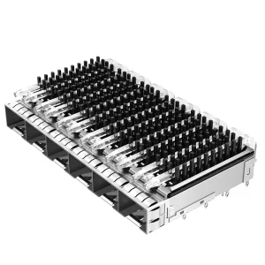
To meet the demands of modern high-speed data transmission, SFP ganged cages have evolved significantly from basic metal enclosures. Modern designs incorporate several key innovations:
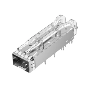
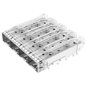
Proprietary clear polycarbonate optical light pipes are integrated directly over the top of the cage assembly. This allows real-time LED status monitoring of individual ports directly on the bezel display, eliminating the need for separate panel indicator assemblies.
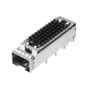
Our cages are compatible with custom heatsinks featuring optimized fin geometries. These designs maximize heat convection under low-airflow conditions, lowering the internal junction temperature of SFP+ modules by up to 12°C compared to standard configurations.
Strategically placed elastic spring finger configurations establish redundant grounding contact paths to the chassis cutout. This reduces high-frequency EMI leakage up to 40 GHz, ensuring compliance with strict FCC and CE electromagnetic emission standards.
These innovations are supported by a rigorous quality control framework. Each manufacturing batch undergoes comprehensive testing, including thermal cycling, vibration, mating cycle endurance, and contact resistance checks. Our automated precision stamping and assembly processes ensure mechanical tolerances are held to within +/- 0.05 mm, guaranteeing compatibility with all major transceiver brands.
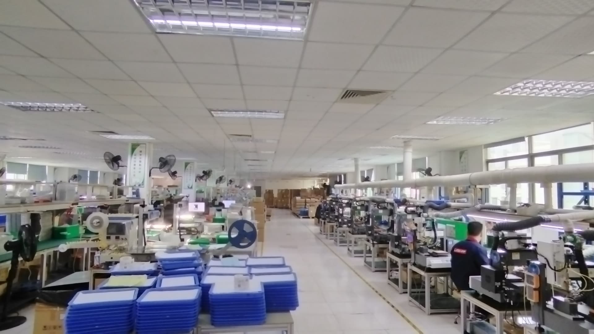
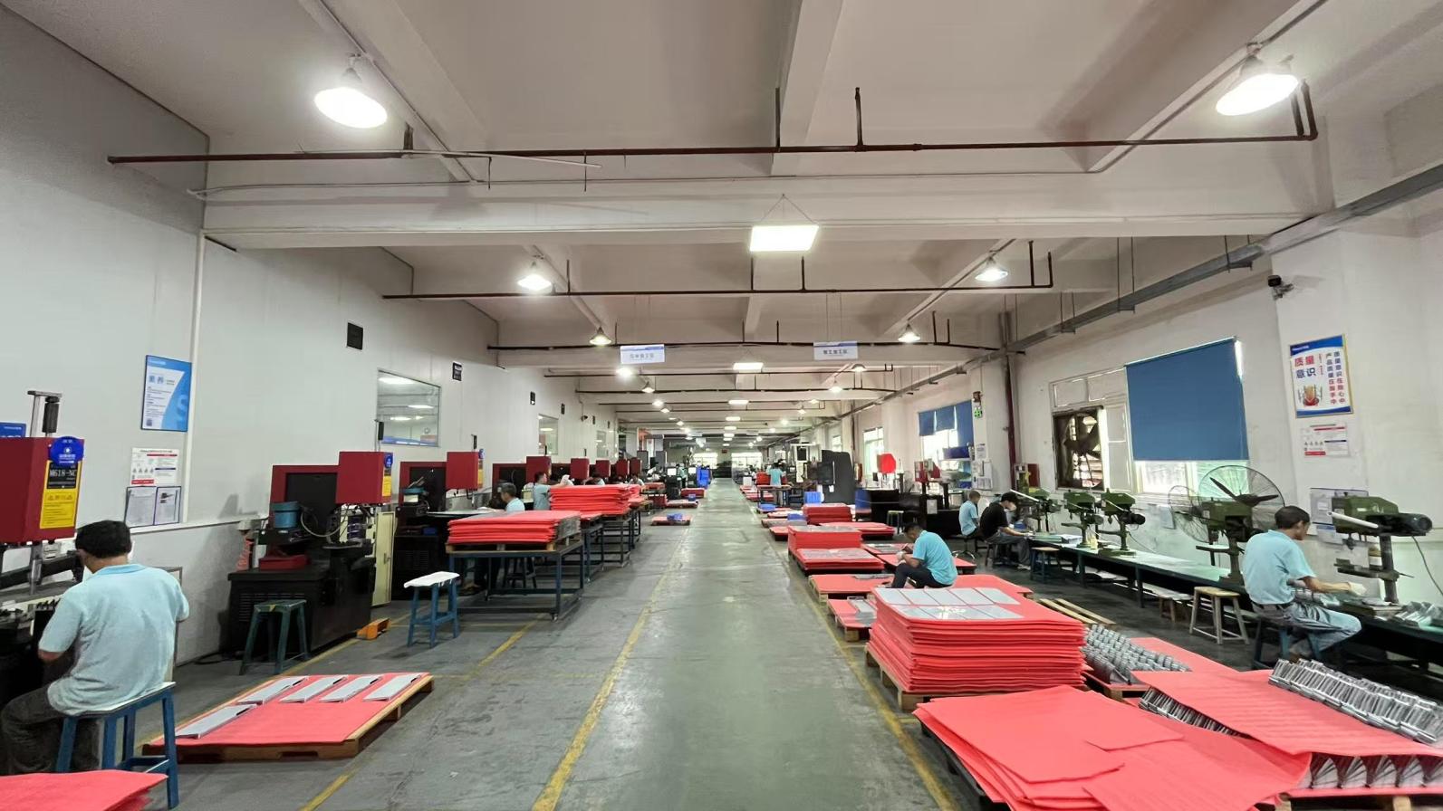
FiberNova Optical Communication Tech Co., Ltd. (FiberNovaTransceivers.com) is an optical transceiver and interconnect components manufacturer established in 2016. Operating a modern production facility covering approximately 380㎡, the company delivers high-speed optical communication solutions to data centers and telecom operators worldwide.
With over 6 years of export experience and 12 years of industry expertise, FiberNova has developed capabilities in R&D, manufacturing, and international trade. The company achieves an annual export revenue of approximately USD 8–15 million, supplying customers across North America, Europe, Southeast Asia, and the Middle East.
Our quality management system is based on strict testing protocols, including 100% optical performance testing, temperature cycling tests, and signal integrity inspection before shipment. The quality assurance team consists of 45 professional QC staff, ensuring all products meet international IEEE and MSA compatibility standards.
FiberNova supports OEM and ODM projects worldwide through an experienced export sales team. The company maintains partnerships with more than 1,200 supply chain partners, ensuring stable procurement of chips, lasers, and optical components. Backed by 65 engineers, our R&D team focuses on high-speed transmission technologies, including 10G, 25G, 100G, 400G, and 800G optical modules.
Ganged SFP cages are key components in high-speed networking systems. The choice of cage configuration depends on the design priorities of the target application:
By selecting the appropriate configuration—balancing port density, thermal management options, and EMI shielding—designers can ensure long-term system reliability and stable signal integrity across all optical links.
Answers to common mechanical and electrical questions from hardware integration and design engineers.
A ganged cage layout positions a single row of ports side-by-side (1xN), keeping the overall height low and allowing direct thermal connection to top-mounted heatsinks. A stacked configuration places two rows of ports on top of each other (2xN), doubling port density for a given width but increasing vertical height and presenting more complex thermal routing challenges for the lower row of modules.
Press-Fit compliant pins use elastic deformation to establish a high-force, solderless electrical connection in the PCB through-holes. This eliminates the thermal stress associated with wave soldering, simplifies PCB rework, and avoids common solder defects such as bridging and cold joints.
The EMI spring fingers contact the perimeter of the bezel opening, establishing a continuous ground connection around the cage assembly. This grounds high-frequency currents and forms a Faraday cage that minimizes radiated emissions, helping the host system meet FCC Part 15 and EN 55022 Class B standards.
Heatsink selection depends on available vertical chassis height, the expected power consumption of the transceiver modules (e.g., 1.5W for SFP+ vs 2.5W+ for SFP28), and internal airflow velocity. Systems with lower airflow typically require taller fins or pin-fin configurations to maximize natural and forced convection.
Yes. All our SFP, SFP+, and SFP28 cages are designed and manufactured in accordance with the INF-8074i and SFF-8432 Multi-Source Agreements (MSA). This ensures mechanical compatibility with standard-compliant transceivers from any manufacturer.
Our light pipes are routed through dedicated channels outside the EMI shielding envelope of the cage. They are designed to prevent light leakage while ensuring the grounding integrity of the cage body is not compromised, preventing any degradation in shielding effectiveness.
The press-fit pins are typically plated with a nickel underplate followed by matte tin or selective gold. Tin plating ensures low contact resistance with the copper-plated PCB through-holes, while the nickel barrier prevents copper migration and solder joint degradation.
Our engineering team supports customized development, including modifying light pipe configurations, adapting heatsink designs, and customizing pin patterns for specific layout requirements. We utilize modern mechanical and thermal simulation tools to verify performance before tool production.
Complete your high-speed port layout designs with these additional models.