Selecting a single mode transceiver is more than matching a port and choosing the longest advertised distance. In real deployments, small details decide whether a link remains stable after installation. Fiber type, wavelength, connector polish, transmission speed, and optical budget must work together. A module that appears suitable on a product page may still fail beside an older switch, a mismatched patch cable, or a crowded rack with rising temperatures.
This guide introduces seven practical tips for making a better choice. It considers compatibility, reach, environmental conditions, digital diagnostics, manufacturer documentation, testing, and long-term support. These factors reflect common concerns in data centers, campus networks, telecom rooms, and industrial cabinets. Reliable decisions should come from verified specifications, not attractive claims alone. Check the datasheet. Measure the link.
Experience also teaches an uncomfortable lesson: the cheapest transceiver is rarely the cheapest network component. A failed optic can interrupt traffic, delay troubleshooting, and consume hours of engineering time. Yet expensive branding does not guarantee success either. I have seen well-known modules perform poorly when installers ignored connector cleanliness or power limits. That is why careful validation matters. Confirm the switch’s coding requirements, compare the optical parameters, and test the installed link before full deployment. Some recommendations may need adjustment for unusual distances or harsh sites. No checklist replaces judgment. These seven tips offer a disciplined starting point for selecting a single mode transceiver that fits today’s network and remains dependable as requirements change.
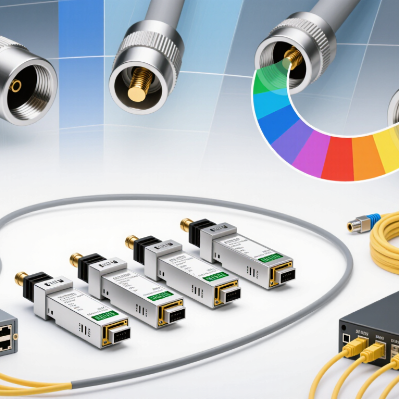
Choosing a single mode transceiver should begin with a clear definition of your network requirements. Estimate the actual link distance, not the distance shown in a project proposal. A 12-kilometer connection needs different optical performance from a 500-meter campus link. Record the required data rate, fiber type, connector design, and operating wavelength. Small details matter.
Check the network architecture before comparing transceiver specifications. Confirm whether the equipment uses duplex or single-fiber transmission. Verify compatibility with the switch, router, fiber panels, and monitoring system. Also review temperature ranges, power limits, and installation conditions. A transceiver in a hot cabinet may need stronger thermal tolerance than one in a cooled data room. Standards compliance improves reliability, but it does not replace testing.
Include future capacity in the requirement sheet. Traffic often grows faster than expected. However, buying the highest-rated module can waste budget and increase power consumption. I have seen teams focus on speed while overlooking optical loss from patch panels and connectors. That mistake is easy to repeat. Calculate the complete link budget, including splices, bends, and maintenance margins. Then test the selected unit with the actual fiber route when possible. Paper specifications look precise. Real cables can be less forgiving. Be willing to revise the plan after testing.
A single-mode transceiver is reliable only when its fiber match is confirmed before installation. Check the fiber type, core specification, connector, and polish required by the network equipment. Single-mode fiber usually uses a narrow core, commonly near 9 micrometers. That detail matters. A connector may fit physically yet fail optically. Inspect the cable label, installation records, and technical datasheet together. Do not trust color alone; cable jackets vary by supplier and environment.
Transmission distance needs equal care. Compare the transceiver’s rated reach with the actual route length, including patch panels and slack loops. Measure the installed link, rather than estimating from a floor plan. Loss from splices, bends, connectors, and dirty end faces can reduce the usable margin. Use an optical power meter or approved test report when possible. For longer links, verify wavelength, launch power, receiver sensitivity, and dispersion limits. A distance number without these values is incomplete.
In field checks, I have seen short links fail because a long-reach module was paired with the wrong fiber path. The purchase sheet looked correct. The assumption was not. Leave engineering margin, but avoid choosing excessive reach without reason. It can complicate diagnostics and waste budget. Record the measured loss and both endpoint specifications before approving the link. I would recheck every unfamiliar route; one overlooked patch cord can change the result.
Compare common single-mode Ethernet transceiver standards by their typical maximum transmission distance. Always verify the wavelength, fiber type, connector, link-loss budget, and equipment standard before deployment.
Key takeaway: OS2 single-mode fiber supports the widest range of long-distance applications, but the transceiver must match the required data rate, wavelength, and reach. Actual distance may be lower because of connector loss, splices, bend loss, and the optical power budget.
Choosing a single mode transceiver starts with wavelength, not price. For most campus links, 1310 nm offers low dispersion and practical reach. For longer spans, 1550 nm usually reduces attenuation. ITU-T G.694.1 defines 100 GHz and 50 GHz channel spacing for optical networks. That matters when selecting CWDM or DWDM equipment. Do not assume every 1550 nm module supports dense wavelength systems.
Data rate must match the switch port and the fiber path. The 2024 Ethernet Alliance roadmap identifies 400G, 800G, and 1.6T as important Ethernet targets. Higher speed often requires parallel lanes, stronger cooling, and tighter link budgets. A 100G module may look economical, but its power draw and reach can differ sharply between designs. Check transmit power, receiver sensitivity, FEC requirements, and maximum distance. Measure twice.
Connector choice affects installation time and fault risk. LC duplex connectors remain easy to handle on conventional OS2 fiber. CS, SN, and MDC connectors support higher-density panels, but technicians need compatible adapters and cleaning tools. Connector fit matters. Inspect end faces before insertion. Dust can create several decibels of loss, especially on high-speed links. I would also verify digital monitoring accuracy, operating temperature, and interoperability. Future-proofing sounds sensible, yet buying the fastest option today can waste budget when the network roadmap remains uncertain.
Choosing a single mode transceiver starts with device compatibility, not advertised distance. Confirm the switch or router supports the transceiver’s form factor, data rate, coding, and operating temperature. A module may fit the cage physically but still fail during initialization.
Check the optical details carefully. Match the transceiver with OS1 or OS2 single-mode fiber, then verify wavelength, connector type, and transmission direction. Duplex links commonly use two fibers, while bidirectional links may use one fiber with paired wavelengths. Check the optical power budget, receiver sensitivity, and maximum reach. For example, a 10-kilometer rating may assume clean fiber and low loss. Dust, sharp bends, and several patch panels can reduce that margin quickly. Small details matter.
Use the equipment’s compatibility list and compare it with the transceiver datasheet. Look for digital diagnostics, temperature limits, power consumption, and alarm thresholds. A live test is even better. Record link levels before and after installation. I have seen a link pass traffic but show unstable receive power later. That result was easy to dismiss. It should not have been. Also inspect the connectors under magnification, because a faint contamination mark can create unexpected errors. Leave room for real-world loss, not just the ideal specification.
| Tip | Selection Dimension | What to Check | Typical Single Mode Requirement | Why It Matters |
|---|---|---|---|---|
| 1 | Host Device Compatibility | Confirm the switch, router, storage system, or optical platform supports the transceiver form factor, port speed, coding, and operating temperature. | Match the module to the port standard, such as SFP for 1 Gb/s, SFP+ for 10 Gb/s, SFP28 for 25 Gb/s, or QSFP-based designs for higher aggregate rates. | A physically compatible module may still be rejected if the host system does not support its speed, firmware profile, or electrical interface. |
| 2 | Fiber Type and Connector | Check that the module is designed for single mode fiber and that the connector matches the installed patch cable and panel. | Use 9/125 µm single mode fiber; LC duplex is common for two-fiber links, while LC simplex or duplex configurations vary by optical design. | Using multimode fiber or an incorrect connector arrangement can cause excessive loss, installation errors, or complete link failure. |
| 3 | Wavelength Matching | Compare the transmit wavelength with the receiving module and fiber system. For bidirectional modules, verify the paired transmit and receive wavelengths. | Common single mode windows include 1310 nm for shorter metropolitan links and 1550 nm for longer-distance applications. | The wavelength affects fiber attenuation, dispersion behavior, optical budget, and whether two ends can communicate correctly. |
| 4 | Transmission Distance | Choose a rated reach that covers the actual fiber route, including patch panels, splices, connectors, and future route changes. | Typical single mode options may cover approximately 2 km, 10 km, 20 km, 40 km, or 80 km, depending on speed and optical budget. | A rating that is too short may produce an unstable link; a much longer-rated optic may add cost without improving a short connection. |
| 5 | Optical Power Budget | Compare the transmitter output, receiver sensitivity, and maximum received power with the total estimated link loss. | Use the formula power budget = minimum transmit power − receiver sensitivity. Allow additional margin for connectors, splices, aging, and repairs. | The link should have sufficient margin without exceeding the receiver's maximum input power, which can cause errors or optical damage. |
| 6 | Optical Performance and Diagnostics | Review transmit power, receiver sensitivity, extinction ratio, dispersion limits, and whether digital optical monitoring is supported by the host. | For a 10 Gb/s single mode link, verify that the specified reach and dispersion limits match the fiber route. Digital monitoring can report temperature, voltage, bias current, and optical power. | Performance specifications predict link reliability, while diagnostics simplify fault isolation and help identify degraded optics or cabling. |
| 7 | Operating Conditions and Safety | Check the temperature grade, power consumption, laser safety classification, and installation environment before deployment. | Commercial modules commonly support about 0°C to 70°C; industrial applications may require a wider range such as −40°C to 85°C. | Temperature outside the specified range can affect laser output, receiver sensitivity, service life, and overall link stability. |
Practical check: Before installation, verify both endpoint specifications, the fiber route loss, connector type, wavelength pair, and the transceiver's operating temperature range.
A single mode transceiver should match the network’s distance, fiber type, and operating environment. Check its temperature range before installation in a rooftop cabinet. Tiny details matter. Verify the connector, wavelength, transmission distance, and data rate against your equipment list. A mismatch may work briefly, then create unstable links during heavy traffic.
Reliability deserves evidence, not attractive promises. Review test reports, failure-rate data, warranty terms, and product traceability. Ask whether each unit passes optical power and sensitivity checks. Standards compliance is equally important. Confirm alignment with applicable optical, Ethernet, safety, and electromagnetic compatibility requirements. Independent laboratory records offer stronger assurance than vague “compliant” wording. I once trusted a specification sheet too quickly. The module met the headline speed but performed poorly in a warm enclosure.
Total cost includes more than the purchase price. Consider power consumption, monitoring features, replacement time, installation labor, and stock requirements. A slightly cheaper transceiver can become expensive after repeated link failures. Check digital diagnostics, because early warnings can reduce emergency maintenance. Compare realistic operating costs over three to five years. Also review interoperability with existing network equipment, not only laboratory compatibility. Keep a small spare inventory for critical links. That choice may seem excessive. It can prevent a long outage.
Use documented acceptance tests before full deployment. Record optical levels, error counts, temperature readings, and link stability. Recheck them after several weeks. Field conditions often reveal weaknesses that specifications miss. When evidence conflicts, pause and investigate rather than selecting the lowest quotation.
Record the actual link distance, data rate, fiber type, connector, and operating wavelength. Measure the installed route, not the proposal estimate. Small details matter. Include future capacity, but avoid buying unnecessary performance.
Check the fiber type, core specification, connector, and polish requirements. Single-mode fiber commonly has a narrow core near 9 micrometers. A connector may fit physically yet fail optically. Do not trust jacket color alone.
Measure the complete route, including patch panels, slack loops, splices, and maintenance sections. A floor plan estimate can be misleading. Use an optical power meter or an approved test report when possible. One overlooked patch cord can change the result.
Review wavelength, launch power, receiver sensitivity, dispersion limits, and total optical loss. Include losses from connectors, bends, splices, and dirty end faces. Leave an engineering margin. Do not rely on distance numbers alone.
Check temperature limits, power consumption, cabinet ventilation, and installation conditions. A rooftop cabinet may become much hotter than a cooled data room. Thermal stress can create unstable links during heavy traffic. The plan may be wrong.
Review test reports, failure-rate information, warranty terms, and product traceability. Confirm optical power and receiver sensitivity testing for each unit. Independent laboratory records are stronger than vague compliance claims. Promises are not evidence.
Confirm applicable optical, Ethernet, safety, and electromagnetic compatibility requirements. Check interoperability with switches, routers, fiber panels, and monitoring systems. Laboratory compatibility does not guarantee field performance. Test the actual route.
Include purchase price, power use, monitoring features, replacement time, labor, and spare inventory. Compare realistic operating costs over three to five years. A cheaper unit may become expensive after repeated failures. Keep limited spares for critical links.
Record optical levels, error counts, temperature readings, and link stability. Test the selected unit with the actual fiber route whenever possible. Recheck performance after several weeks. Paper specifications can mislead.
Choosing the right single mode transceiver begins with a clear understanding of your network requirements, including link distance, bandwidth, fiber infrastructure, and expected traffic growth. Confirm that the transceiver matches the installed fiber type and can support the required transmission distance without compromising signal quality. It is also important to compare operating wavelengths, data rates, and connector types so the module fits both the network design and physical cabling.
Before making a decision, verify device compatibility and review key optical specifications such as transmit power, receiver sensitivity, and operating temperature. Reliability should also be assessed through compliance with relevant industry standards, suitable monitoring features, and a proven design for long-term operation. Finally, consider the total cost rather than the purchase price alone, including installation, maintenance, energy use, and potential replacement needs. A balanced evaluation of performance, compatibility, dependability, and lifecycle value will help ensure the single mode transceiver supports a stable and scalable network.

FiberNova